Categories
{{ selectedCategory.name }}
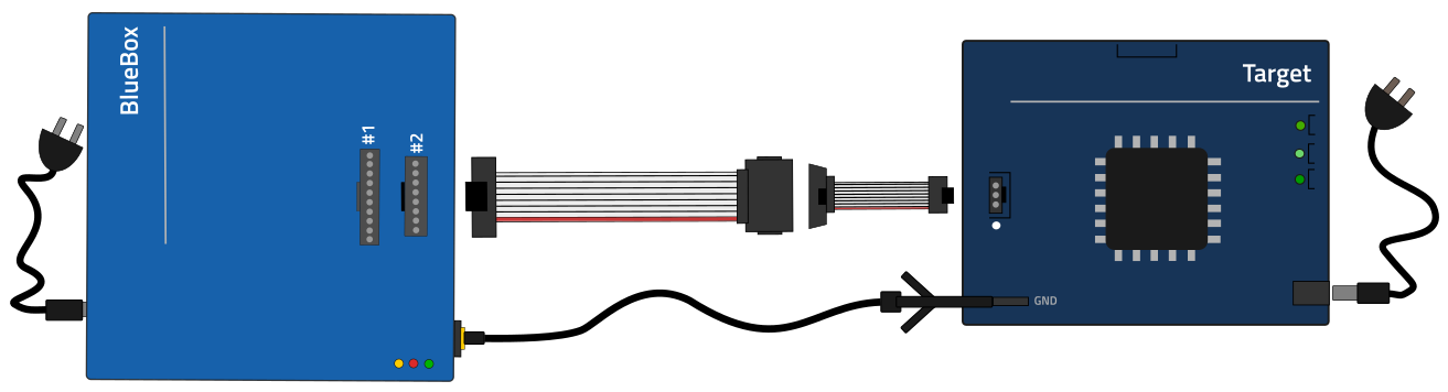
How to connect BlueBox and Target via Debug Adapter?
23-Nov-2023
The Debug Adapter is directly connected to the Target and the other side connects via the ribbon cable to the iC5000/iC5700 connectors. Detailed steps in Hardware Setup and Configuration Tutorial.
Configuration steps:
1. Connect the Power supply.
2. Connect the BlueBox and PC.
3. Connect the Grounding wire.
4. Connect the BlueBox and the Target via Debug Adapter.
5. Power on/off procedure.
More resources:
- Hardware Setup and Configuration - Tutorial
- Connecting the BlueBox to an Embedded Target – Debug Adapter - Video Tutorial
Was this answer helpful?
Sorry this article didn't answer your question, we'd love to hear how we can improve it.
Note: This form won't submit a case. We'll just use it to make this article better.
Similar topics
{{ topic.Title }} {{ topic.Ddate | formatDate }}
{{ topic.Content }}
No similar topics found!